Selection of inverter starting resistor, selection of inverter pre-charge resistor-huaju electronics
Release time:
2024-03-07
The medium and small power general-purpose frequency converter is generally a voltage type frequency converter, which adopts the AC-DC-AC working mode. When the inverter is just powered on, because the filter capacitor capacity on the DC side is very large, the current is equivalent to a short circuit at the moment of charging, and the current will be very large. If there is no charging resistor between the rectifier bridge and the electrolytic capacitor, it is equivalent to a short circuit of 380V power supply directly to the ground, and the instantaneous rectifier bridge will blow up through infinite current. With the current limiting of the charging resistor, if there is no relay or other components, the charging resistor consumes a lot of power. For example, for a 22kW frequency converter, there is at least 45A of current on the PN terminal (DC bus). If there is a problem with the "control circuit" part (such as the quality of relays or thyristors, etc.), the charging resistor will be broken due to too much heat after the inverter runs for a while. Therefore, the charging resistor is connected in series in the charging circuit to limit the current at the moment of energization to protect some input circuit devices such as rectifiers. Some books are also called buffer resistors or starting resistors. SIEMENS 6SE701G variable frequency starting circuit as shown in the figure.
1. Charging resistance
The medium and small power general-purpose frequency converter is generally a voltage type frequency converter, which adopts the AC-DC-AC working mode. When the inverter is just powered on, because the filter capacitor capacity on the DC side is very large, the current is equivalent to a short circuit at the moment of charging, and the current will be very large. If there is no charging resistor between the rectifier bridge and the electrolytic capacitor, it is equivalent to a short circuit of 380V power supply directly to the ground, and the instantaneous rectifier bridge will blow up through infinite current. With the current limiting of the charging resistor, if there is no relay or other components, the charging resistor consumes a lot of power. For example, for a 22kW frequency converter, there is at least 45A of current on the PN terminal (DC bus). If there is a problem with the "control circuit" part (such as the quality of relays or thyristors, etc.), the charging resistor will be broken due to too much heat after the inverter runs for a while. Therefore, the charging resistor is connected in series in the charging circuit to limit the current at the moment of energization to protect some input circuit devices such as rectifiers. Some books are also called buffer resistors or starting resistors. SIEMENS 6SE701G variable frequency starting circuit as shown in the figure.
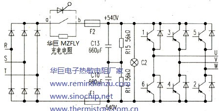
After the charging is completed, the control circuit short-circuits the resistor through the contact of the relay or the thyristor to complete the power-on process of the inverter. If the AC input power of the inverter is frequently turned on and off, or the contact of the bypass contactor is not in good contact or the conduction resistance of the thyristor becomes larger, repeated charging or charging time is too long will cause the charging resistor to burn out. Therefore, before replacing the charging resistor, the reason must be found out before the inverter can be put into use.
However, some inverters have a voltage detection and frequency reduction action during startup. If the contactor coil lead terminal is loose and causes poor contact, the contactor fails to close, and the large current during startup forms a large voltage drop on the charging resistor. The sharp drop of the DC voltage of the main circuit is detected by the voltage detection circuit, and the CPU will make a frequency reduction instruction under no load or light load, the detection circuit will "report" the undervoltage fault in time, and the CPU will stop immediately for protection. The resistance is too late to burn, and the frequency converter has been shut down for protection.
So, how to choose the resistance of the charging resistor?
After 380V AC is rectified, the electrolytic capacitor is charged through the charging resistor. When the auxiliary power supply is charged to a certain value (such as DC200V), the auxiliary power supply starts to supply power to the control board, allowing the control board to work so that the relay or thyristor is turned on, and the charging resistor no longer works. At the moment of startup, the smaller the charging resistance, the greater the current flowing through the rectifier bridge. There are often beginners inverter repairers call to consult, replace the charging resistor, the inverter is turned on, the rectifier bridge will be blown up immediately, is the charging resistor selection too small.
In fact, at the moment of starting up, it is not because the selected charging resistor R is small, but because R is too large that the rectifier bridge is blown up. Because after the inverter is turned on, the current is charged through the charging resistor. When the charged electricity is enough for the auxiliary power supply to start (for example, 200V), the CPU works and sends a signal to the relay or thyristor to turn on. When the relay is turned on, if the voltage at point B of the relay is very low (greater than 200V), and the voltage at point a is AC380V directly rectified, it is about DC540V, so the voltage difference between the two ends of a and B is very large. At the moment of triggering and conduction, the current is very large, just like a small resistance between A and B, and a voltage of several hundred volts is added in an instant, so the current flowing through the rectifier bridge is far greater than the rated current of the rectifier bridge, so the rectifier bridge is blown up.
The greater the inverter power, the smaller the charging resistance. Because the greater the power of the inverter, the greater the capacity of the electrolytic capacitor, and the greater the capacity of the capacitor, the longer the charging time. RC determines the charging time. If you want the charging time to be as short as possible, you can only take the charging resistor R as small as possible. General charging resistance selection: the maximum value is best not to exceed 300 Ω, the minimum value is best greater than or equal to 10 Ω, high-power inverter selection charging resistance is small, small power inverter charging resistance is large.
2. Energy storage capacitor
Selection of storage capacitor capacity: the general choice of empirical value is ≥ 60 μF/A. For example, a 15kW inverter has a rated current of 30A, and the required capacitor capacity is ≥ 60 μF/A× 30A, I .e. at least 1800 μF, so four 2200 μF (two parallel two strings) or two 4700μF capacitors (two series) are generally selected. Of course, the brand of the selected capacitor must also be considered. The quality of different brands will vary greatly.
Some people only replace the damaged inverter module when repairing the inverter, and it often doesn't take long for the module to be damaged again. This situation will complain about the poor quality of the module, the poor user environment, etc. In fact, the most important reason is that they did not find out the reason for the damage of the inverter module and did not completely eliminate the hidden trouble.
The damage of the inverter module, in addition to the load for a long time overload, poor heat dissipation and lightning impulse, the internal reasons, the capacity reduction, loss of capacity and failure of the capacitor, is the fatal killer of its damage! Its harmfulness cannot be ignored. When the capacity decreases, the lighter one shows poor load capacity. When the load increases, it often causes the DC circuit to fail to overvoltage. When the capacitor is further damaged, it will form a fatal blow to the inverter module. At this time, the voltage detection circuit has no time to respond and report the failure, resulting in damage to the inverter module.
After the capacitor is poor or fails (or the capacity becomes smaller), there is no abnormality on the surface when running with a small power load (large horse-drawn trolley), but the situation is different when a large power load is connected (full load operation). At this time, the DC circuit of the frequency converter has completely (or partially) lost the energy storage filtering capacity. The DC circuit is pulsating DC with a frequency of 300Hz, and the current suction when the motor starts increases the pulsating component of the pulsating current. This is one of the reasons why a small resistance is unfavorable to a high-voltage capacitor and a large resistance is easy to explode. In addition, if the back EMF of the motor winding or a certain output carrier of the frequency converter just falls within the variation range of the pulsating DC, the two are superimposed on each other, and the rapid change of the pulsating current in the whole system just falls on a certain frequency point, the distributed inductance and distributed capacitance in the circuit are added from time to time, and the addition and interaction of various unfavorable factors make the dynamic energy in the circuit rise sharply, instantaneous dangerous resonance overvoltage appears at this time! The IGBT tube in the inverter module and the spike voltage absorption diode in the circuit have a certain or even large amount of voltage under normal conditions, but under the high voltage impact several times higher than the voltage resistance at this time, they have no fighting power and are very fragile. It is not surprising that overvoltage burst and breakdown short circuit are not surprising. Although the inverter has a perfect voltage or current protection detection circuit, but if you often have to face such instantaneous voltage distortion, it is powerless, or sometimes unable to make a timely response.
However, the bad faults of energy storage capacitors are often hidden, which can be said to be soft faults and easy to be ignored. Some capacitors seem to have no problem measuring their capacity, and they can also run, but they are a big hidden danger in operation. In particular, if the capacitor in the high-power frequency converter is operated in a harsh environment for a long time, its lead-out electrode will be subjected to large current charging and discharging impact of hundreds of Hz for many years, resulting in corrosion and oxidation phenomena of different degrees. When measured by a capacitance meter, the capacity is not abnormal. However, when connected to the circuit, the DC circuit voltage drops due to the increase of internal resistance of charging and discharging, and the frequency converter cannot work normally, thus causing the maintenance personnel to make misjudgment and detours. Again, it is emphasized that resonant overvoltage is prone to burst after the loss of energy storage capacitor.
NTC thermistors are not always the inevitable choice for inrush current limiters (ICLs) in power supplies. In applications with particularly stringent temperature and power requirements, PTC thermistors can provide more reliable protection. Huagu Technology (SINOCHIP) PTC ICL additional benefit is the ability to provide short-circuit protection.
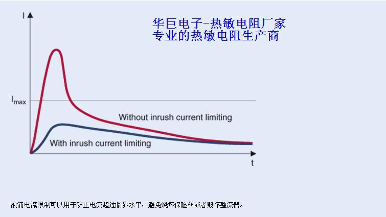
When turning on electrical equipment such as the drive system, inverter or power supply, there will always be a large current. Because excessive surge current can damage sensitive components such as the rectifier in the power supply or burn out the fuse, protective measures need to be taken (Figure 1). There are two basic ways to limit the inrush current: simply placing a protective device in the power circuit as an inrush current limiter (ICL), or using an active bypass circuit after the inrush current peak has subsided. These two approaches are also referred to as passive and active ICL circuits, respectively. The choice of inrush current suppression technique for a particular application depends on a number of factors. The most important are the power of the power supply, the frequency of the inrush current to which the equipment is subjected, the operating temperature range, and the system cost requirements.
Figure 1: Inrush current with and without ICL
Passive inrush current limiting
For small power supplies with a power rating of up to a few watts, the simplest practical inrush current limiting solution is a common resistor in series with the load, but for power supplies with higher power ratings, the power loss of the fixed resistor can significantly affect the overall efficiency. In these cases, the use of NTC thermistors as passive current limiting has become a standard ICL solution (Figure 2).
Figure 2: Passive inrush current limiting using NTC ICL

Once the NTC thermistor is heated, its initial high resistance will be reduced to a negligible level. This feature makes NTC ICL a standard ICL solution in power supplies with a rated power of up to about 500W. NTC thermistors have higher resistance at lower temperatures and lower resistance at higher temperatures. At lower temperatures, the higher initial resistance of the NTC ICL can effectively absorb the peak surge current. Due to the effect of the current load and the consequent self-heating, the ICL resistance then decreases to a few percent of its room temperature resistance. This feature reduces the power consumption of the ICL under continuous operation, so that the NTC ICL can remain in the circuit after the capacitor is fully charged. Finally, the cost of using NTC ICL is low and the solution is easy to implement.
Low-loss solutions focused on higher power level applications The design of power supplies is increasingly focused on eliminating power loss as much as possible. Once the rated power exceeds 500W, the disadvantages of the passive circuit solution become very obvious. If the ICL is always in series with the load, the power loss will be very large. The higher the power rating of the equipment, the longer the typical operating time and the more significant the incidental power loss. Assuming that the power loss of NTC ICL accounts for 1% of the total power of the device and the efficiency of the power supply is 92%, about 12.5 of the total loss is caused by NTC.
Active inrush current limiting Therefore for higher power levels, it is standard practice to use a relay or thyristor to bypass the ICL once the inrush current peak has subsided. Depending on the application requirements, the active inrush current limiting circuit can use power resistors, NTC thermistors or PTC thermistors (Figure 3) as ICL components. For example, PTC thermistors are often used in plug-in on-board chargers (OBC) for hybrid or electric vehicles. The rated power of such chargers usually reaches several kilowatts. While the benefits of active inrush current limiting are most apparent for power ratings greater than 500W, this approach may also be necessary to improve performance for lower power level applications. Although the system cost of active inrush current limiting itself is somewhat higher, it can reduce power loss for lower power rating applications, and can use relatively inexpensive lower rating switches and semiconductor devices.
Figure 3: Active inrush current limiting

When to Use a PTC Thermistor as an ICL In some applications, the use of a PTC thermistor as an ICL can provide excellent performance. The resistance of the NTC ICL at power-on depends on the ambient temperature. At a lower ambient temperature, the resistance of the NTC thermistor will be higher, resulting in lower charging current and longer charging time. On the other hand, a higher ambient temperature limits the ability of the NTC ICL to suppress inrush current because the NTC thermistor is already in a low resistance state. This temperature dependence can be problematic for some applications, particularly those with a wide operating temperature range. For example, an outdoor power supply used in the northern winter may never rise hot enough to make the resistance drop low enough. On the contrary, the hot water circulation pump may be very hot when started, which will make the NTC thermistor unable to limit the inrush current. After the system is shut down, the cooling time of NTC thermistors usually varies from 30s to 120s, depending on the specific equipment, installation method and ambient temperature. The charging current can only be limited again when the NTC ICL has cooled down completely. In many cases, this cooling time is already fast enough; however, it is sometimes necessary to effectively limit the inrush current before the NTC has cooled sufficiently. This may occur in the rapid discharge of the DC link capacitor, which occurs in inverter-driven household appliances such as new washing machines and dryers. The necessary cooling time after a brief power outage is very critical. Therefore, the active inrush current limiting design must always take into account the occurrence of inrush current peaks when all possible NTC ICLs are still in the low resistance state. In both cases, SINOCHIP PTC thermistors can provide an effective inrush current limiting scheme.
Built-in self-protection function
Under normal operating conditions, the PTC ICL is used as an ordinary resistor. When the power is turned on and the temperature of the component is the same as the ambient temperature, the resistance value of PTC ICL varies from 20 ohms to 500 ohms depending on the model. This is sufficient to limit the surge current peaks. Once the DC link capacitor is fully charged, the PTC ICL is bypassed,
If the charging circuit fails, the special function of the PTC thermistor can protect the circuit. When current passes through the element, the temperature of the PTC thermistor increases and the resistance increases significantly. Therefore, thanks to its self-protection function, PTC thermistors have inherent advantages in the following failure modes:
-Capacitor short circuit
-The current limiting element is not bypassed (switching element failure) when the DC link capacitor is charged.
All these failure modes have one thing in common: the current limiting element is thermally stressed. There are two ways to ensure that the ICL element will not be damaged in similar situations: use a power resistor with sufficient power rating or use a PTC thermistor. The design of the SINOCHIP PTC ICL allows it to operate when directly connected to the supply voltage of the maximum rated voltage without additional current limiting measures, because the PTC ICL has a self-protection function. In the event of an excessive current such as a short circuit, the temperature of the PTC increases, causing its resistance to rise significantly, so that the PTC thermistor itself can limit the current to a non-critical level (Figure 4).
Figure 4: Current curve when the capacitor is short-circuited
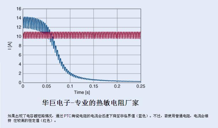
If a capacitor short circuit occurs, the current through the PTC ceramic resistor drops rapidly to a non-critical value (blue). However, if a normal resistor is used, the current will be maintained at a high constant value (red).
SINOCHIP PTC thermistors have some key advantages as ICL components for active inrush current limiting in a number of applications:
-Its ICL function will not be affected by extreme operating temperatures.
-Once the load is turned off, effective inrush current limiting can be achieved, and cooling is already carried out during normal operation.
-Self-protection against current overload caused by circuit fault.
Thanks to the broad product portfolio of SINOCHIP ICL, you can reliably protect your power supply from high inrush currents and short circuits under harsh temperature conditions.
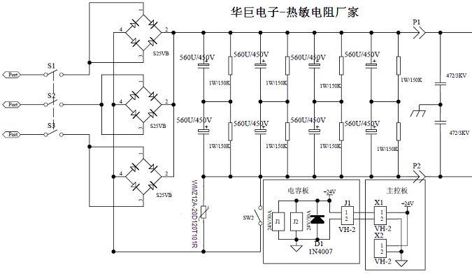
Charging control circuit of energy storage capacitor
Self-protective charging resistors are based on PTC (positive temperature coefficient) ceramics and are used to smooth capacitors in power supplies. When a short circuit occurs, they limit the current to a safe level.
Ordinary resistors are often used to limit current when charging capacitors. However, there are technical risks. For example, when shorting a capacitor, the resistor will continue to be exposed to high power levels if the capacitor is shorted or the relay fails. This may cause the resistor or the entire system to be destroyed. Huagu Electronics uses the new MZFLY series charging resistor based on PTC ceramics, and has now developed a professional solution: while protecting itself, it also achieves a relatively compact size. As shown in the following table,
Main technical parameters
| Model |
Zero power resistor R25 |
Maximum voltage |
Heat capacity |
Maximum non-actuating energy |
Working temperature |
|||
| (Ω) |
Vmax |
Cth(J/K) |
ENon(J) |
(℃) |
||||
| (Vac) | VDC | 25℃ |
40℃ | 60℃ | ||||
| Power frequency voltage 260Vac |
||||||||
| BPFLY-07D120T70RH-260 |
70 |
260 |
370 |
0.15 |
14 | 12 | 9 |
-55~ 85 |
| BPFLY-07D120T80RH-260 |
80 |
260 |
370 |
0.15 |
14 | 12 | 9 |
|
| BPFLY-07D120T101RH-260 |
100 |
260 |
370 |
0.15 |
14 | 12 | 9 |
|
| BPFLY-07D120T121RH-260 |
120 |
260 |
370 |
0.15 |
14 | 12 | 9 |
|
| BPFLY-07D120T151RH-260 |
150 |
260 |
370 |
0.15 |
14 | 12 | 9 |
|
| BPFLY-07D120T201RH-260 |
200 |
260 |
370 |
0.15 |
14 | 12 | 9 |
|
| BPFLY-07D120T251RH-260 |
250 |
260 |
370 |
0.15 |
14 | 12 | 9 |
|
| BPFLY-07D120T401RH-260 |
400 |
260 |
370 |
0.15 |
14 | 12 | 9 |
|
| BPFLY-07D120T501RH-260 |
500 |
260 |
370 |
0.15 |
14 | 12 | 9 |
|
| BPFLY-07D120T102RH-260 |
1000 |
260 |
370 |
0.15 |
14 | 12 | 9 |
|
| BPFLY-08D120T70RH-260 |
70 |
260 |
370 |
0.3 |
28 | 24 | 18 |
|
| BPFLY-08D120T80RH-260 |
80 |
260 |
370 |
0.3 |
28 | 24 | 18 |
|
| BPFLY-08D120T101RH-260 |
100 |
260 |
370 |
0.3 |
28 | 24 | 18 |
|
| BPFLY-08D120T121RH-260 |
120 |
260 |
370 |
0.3 |
28 | 24 | 18 |
|
| BPFLY-08D120T151RH-260 |
150 |
260 |
370 |
0.3 |
28 | 24 | 18 |
|
| BPFLY-08D120T201RH-260 |
200 |
260 |
370 |
0.3 |
28 | 24 | 18 |
|
| BPFLY-08D120T251RH-260 |
250 |
260 |
370 |
0.3 |
28 | 24 | 18 |
|
| BPFLY-08D120T401RH-260 |
400 |
260 |
370 |
0.3 |
28 | 24 | 18 |
|
| BPFLY-08D120T501RH-260 |
500 |
260 |
370 |
0.3 |
28 | 24 | 18 |
|
| BPFLY-08D120T102RH-260 |
1000 |
260 |
370 |
0.3 |
28 | 24 | 18 |
|
| BPFLY-09D120T70RH-260 |
70 |
260 |
370 |
0.4 |
38 | 32 | 24 |
|
| BPFLY-09D120T101RH-260 |
100 |
260 |
370 |
0.4 |
38 | 32 | 24 |
|
| BPFLY-09D120T121RH-260 |
120 |
260 |
370 |
0.4 |
38 | 32 | 24 |
|
| BPFLY-09D120T151RH-260 |
150 |
260 |
370 |
0.4 |
38 | 32 | 24 |
|
| BPFLY-09D120T201RH-260 |
200 |
260 |
370 |
0.4 |
38 | 32 | 24 |
|
| BPFLY-09D251T251RH-260 |
250 |
260 |
370 |
0.4 |
38 | 32 | 24 |
|
| BPFLY-09D501T501RH-260 |
500 |
260 |
370 |
0.4 |
38 | 32 | 24 |
|
| BPFLY-09D120T102RH-260 |
1000 |
260 |
370 |
0.4 |
38 | 32 | 24 |
|
| BPFLY-11D120T10RH-260 |
10 |
260 |
370 |
0.6 |
57 | 48 | 36 | |
| BPFLY-11D120T15RH-260 |
15 |
260 |
370 |
0.6 |
57 | 48 | 36 | |
| BPFLY-11D120T20RH-260 |
20 |
260 |
370 |
0.6 |
57 | 48 | 36 | |
| BPFLY-11D120T30RH-260 |
30 |
260 |
370 |
0.6 |
57 | 48 | 36 | |
| BPFLY-11D120T50RH-260 |
50 |
260 |
370 |
0.6 |
57 | 48 | 36 | |
| BPFLY-11D120T70RH-260 |
70 |
260 |
370 |
0.6 |
57 | 48 | 36 | |
| BPFLY-11D120T101RH-260 |
100 |
260 |
370 |
0.6 |
57 | 48 | 36 | |
| BPFLY-11D120T151RH-260 |
150 |
260 |
370 |
0.6 |
57 | 48 | 36 | |
| BPFLY-11D120T201RH-260 |
200 |
260 |
370 |
0.6 |
57 | 48 | 36 | |
| BPFLY-11D120T251RH-260 |
250 |
260 |
370 |
0.6 |
57 | 48 | 36 | |
| BPFLY-11D120T401RH-260 |
400 |
260 |
370 |
0.6 |
57 | 48 | 36 | |
| BPFLY-11D120T501RH-260 |
500 |
260 |
370 |
0.6 |
57 | 48 | 36 | |
| BPFLY-11D120T801RH-260 |
800 |
260 |
370 |
0.6 |
57 | 48 | 36 | |
| BPFLY-11D120T102RH-260 |
1000 |
260 |
370 |
0.6 |
57 | 48 | 36 | |
| BPFLY-14D120T6R0H-260 |
6 |
260 |
370 |
1.0 |
95 | 80 | 60 |
|
| BPFLY-14D120T10RH-260 |
10 |
260 |
370 |
1.0 |
95 | 80 | 60 |
|
| BPFLY-14D120T15RH-260 |
15 |
260 |
370 |
1.0 |
95 | 80 | 60 |
|
| BPFLY-14D120T18RH-260 |
18 |
260 |
370 |
1.0 |
95 | 80 | 60 |
|
| BPFLY-14D120T25RH-260 |
25 |
260 |
370 |
1.0 |
95 | 80 | 60 |
|
| BPFLY-14D120T30RH-260 |
30 |
260 |
370 |
1.0 |
95 | 80 | 60 |
|
| BPFLY-14D120T45RH-260 |
45 |
260 |
370 |
1.0 |
95 | 80 | 60 |
|
| BPFLY-14D120T50RH-260 |
50 |
260 |
370 |
1.0 |
95 | 80 | 60 |
|
| BPFLY-14D120T70RH-260 |
70 |
260 |
370 |
1.0 |
95 | 80 | 60 |
|
| BPFLY-14D120T101RH-260 |
100 |
260 |
370 |
1.0 |
95 | 80 | 60 |
|
| BPFLY-14D120T151RH-260 |
150 |
260 |
370 |
1.0 |
95 | 80 | 60 |
|
| BPFLY-14D120T201RH-260 |
200 |
260 |
370 |
1.0 |
95 | 80 | 60 |
|
| BPFLY-14D120T251RH-260 |
250 |
260 |
370 |
1.0 |
95 | 80 | 60 |
|
| BPFLY-14D120T401RH-260 |
400 |
260 |
370 |
1.0 |
95 | 80 | 60 |
|
| BPFLY-14D120T501RH-260 |
500 |
260 |
370 |
1.0 |
95 | 80 | 60 |
|
| BPFLY-14D120T801RH-260 |
800 |
260 |
370 |
1.0 |
95 | 80 | 60 |
|
| BPFLY-14D120T102RH-260 |
1000 |
260 |
370 |
1.0 |
95 | 80 | 60 |
|
| BPFLY-18D120T6R0H-260 |
6 |
260 |
370 |
1.5 |
143 | 120 | 90 |
|
| BPFLY-18D120T10RH-260 |
10 |
260 |
370 |
1.5 |
143 | 120 | 90 |
|
| BPFLY-18D120T15RH-260 |
15 |
260 |
370 |
1.5 |
143 | 120 | 90 |
|
| BPFLY-18D120T18RH-260 |
18 |
260 |
370 |
1.5 |
143 | 120 | 90 |
|
| BPFLY-18D120T25RH-260 |
25 |
260 |
370 |
1.5 |
143 | 120 | 90 |
|
| BPFLY-18D120T30RH-260 |
30 |
260 |
370 |
1.5 |
143 | 120 | 90 |
|
| BPFLY-18D120T45RH-260 |
45 |
260 |
370 |
1.5 |
143 | 120 | 90 |
|
| BPFLY-18D120T50RH-260 |
50 |
260 |
370 |
1.5 |
143 | 120 | 90 |
|
| BPFLY-18D120T70RH-260 |
70 |
260 |
370 |
1.5 |
143 | 120 | 90 |
|
| BPFLY-18D120T101RH-260 |
100 |
260 |
370 |
1.5 |
143 | 120 | 90 |
|
| BPFLY-18D120T151RH-260 |
150 |
260 |
370 |
1.5 |
143 | 120 | 90 |
|
| BPFLY-18D120T201RH-260 |
200 |
260 |
370 |
1.5 |
143 | 120 | 90 |
|
| BPFLY-18D120T251RH-260 |
250 |
260 |
370 |
1.5 |
143 | 120 | 90 |
|
| BPFLY-18D120T401RH-260 |
400 |
260 |
370 |
1.5 |
143 | 120 | 90 |
|
| BPFLY-18D120T501RH-260 |
500 |
260 |
370 |
1.5 |
143 | 120 | 90 |
|
| BPFLY-18D120T801RH-260 |
800 |
260 |
370 |
1.5 |
143 | 120 | 90 |
|
| BPFLY-18D120T102RH-260 |
1000 |
260 |
370 |
1.5 |
143 | 120 | 90 |
|
| BPFLY-20D120T6R0H-260 |
6 |
260 |
370 |
1.9 | 180 | 152 | 114 | |
| BPFLY-20D120T10RH-260 |
10 |
260 |
370 |
1.9 | 180 | 152 | 114 | |
| BPFLY-20D120T15RH-260 |
15 |
260 |
370 |
1.9 | 180 | 152 | 114 | |
| BPFLY-20D120T18RH-260 |
18 |
260 |
370 |
1.9 | 180 | 152 | 114 | |
| BPFLY-20D120T25RH-260 |
25 |
260 |
370 |
1.9 | 180 | 152 | 114 | |
| BPFLY-20D120T30RH-260 |
30 |
260 |
370 |
1.9 | 180 | 152 | 114 | |
| BPFLY-20D120T45RH-260 |
45 |
260 |
370 |
1.9 | 180 | 152 | 114 | |
| BPFLY-20D120T50RH-260 |
50 |
260 |
370 |
1.9 | 180 | 152 | 114 | |
| BPFLY-20D120T70RH-260 |
70 |
260 |
370 |
1.9 | 180 | 152 | 114 | |
| BPFLY-20D120T101RH-260 |
100 |
260 |
370 |
1.9 | 180 | 152 | 114 | |
| BPFLY-20D120T151RH-260 |
150 |
260 |
370 |
1.9 | 180 | 152 | 114 | |
| BPFLY-20D120T201RH-260 |
200 |
260 |
370 |
1.9 | 180 | 152 | 114 | |
| BPFLY-20D120T251RH-260 |
250 |
260 |
370 |
1.9 | 180 | 152 | 114 | |
| BPFLY-20D120T401RH-260 |
400 |
260 |
370 |
1.9 | 180 | 152 | 114 | |
| BPFLY-20D120T501RH-260 |
500 |
260 |
370 |
1.9 | 180 | 152 | 114 | |
| BPFLY-20D120T801RH-260 |
800 |
260 |
370 |
1.9 | 180 | 152 | 114 | |
| BPFLY-20D120T102RH-260 |
1000 |
260 |
370 |
1.9 | 180 | 152 | 114 | |
| BPFLY-22D120T3R3H-260 |
3.3 |
260 |
370 |
2.4 |
228 | 192 | 144 | |
| BPFLY-22D120T4R7H-260 |
4.7 |
260 |
370 |
2.4 |
228 | 192 | 144 | |
| BPFLY-22D120T6R0H-260 |
6 |
260 |
370 |
2.4 |
228 | 192 | 144 | |
| BPFLY-22D120T10RH-260 |
10 |
260 |
370 |
2.4 |
228 | 192 | 144 | |
| BPFLY-22D120T15RH-260 |
15 |
260 |
370 |
2.4 |
228 | 192 | 144 | |
| BPFLY-22D120T18RH-260 |
18 |
260 |
370 |
2.4 |
228 | 192 | 144 | |
| BPFLY-22D120T25RH-260 |
25 |
260 |
370 |
2.4 |
228 | 192 | 144 | |
| BPFLY-22D120T30RH-260 |
30 |
260 |
370 |
2.4 |
228 | 192 | 144 | |
| BPFLY-22D120T45RH-260 |
45 |
260 |
370 |
2.4 |
228 | 192 | 144 | |
| BPFLY-22D120T50RH-260 |
50 |
260 |
370 |
2.4 |
228 | 192 | 144 | |
| BPFLY-22D120T70RH-260 |
70 |
260 |
370 |
2.4 |
228 | 192 | 144 | |
| BPFLY-22D120T101RH-260 |
100 |
260 |
370 |
2.4 |
228 | 192 | 144 | |
| BPFLY-22D120T151RH-260 |
150 |
260 |
370 |
2.4 |
228 | 192 | 144 | |
| BPFLY-22D120T201RH-260 |
200 |
260 |
370 |
2.4 |
228 | 192 | 144 | |
| BPFLY-22D120T251RH-260 |
250 |
260 |
370 |
2.4 |
228 | 192 | 144 | |
| BPFLY-22D120T401RH-260 |
400 |
260 |
370 |
2.4 |
228 | 192 | 144 | |
| BPFLY-22D120T501RH-260 |
500 |
260 |
370 |
2.4 |
228 | 192 | 144 | |
| BPFLY-22D120T801RH-260 |
800 |
260 |
370 |
2.4 |
228 | 192 | 144 | |
| BPFLY-22D120T102RH-260 |
1000 |
260 |
370 |
2.4 |
228 | 192 | 144 | |
| BPFLY-27D120T3R3H-260 |
3.3 |
260 |
370 |
3.75 |
356 | 300 | 225 |
|
| BPFLY-27D120T4R7H-260 |
4.7 |
260 |
370 |
3.75 |
356 | 300 | 225 |
|
| BPFLY-27D120T6R0H-260 |
6 |
260 |
370 |
3.75 |
356 | 300 | 225 |
|
| BPFLY-27D120T10RH-260 |
10 |
260 |
370 |
3.75 |
356 | 300 | 225 |
|
| BPFLY-27D120T15RH-260 |
15 |
260 |
370 |
3.75 |
356 | 300 | 225 |
|
| BPFLY-27D120T18RH-260 |
18 |
260 |
370 |
3.75 |
356 | 300 | 225 |
|
| BPFLY-27D120T25RH-260 |
25 |
260 |
370 |
3.75 |
356 | 300 | 225 |
|
| BPFLY-27D120T30RH-260 |
30 |
260 |
370 |
3.75 |
356 | 300 | 225 |
|
| BPFLY-27D120T45RH-260 |
45 |
260 |
370 |
3.75 |
356 | 300 | 225 |
|
| BPFLY-27D120T50RH-260 |
50 |
260 |
370 |
3.75 |
356 | 300 | 225 |
|
| BPFLY-27D120T70RH-260 |
70 |
260 |
370 |
3.75 |
356 | 300 | 225 |
|
| BPFLY-27D120T101RH-260 |
100 |
260 |
370 |
3.75 |
356 | 300 | 225 |
|
| BPFLY-27D120T151RH-260 |
150 |
260 |
370 |
3.75 |
356 | 300 | 225 |
|
| BPFLY-27D120T201RH-260 |
200 |
260 |
370 |
3.75 |
356 | 300 | 225 |
|
| BPFLY-27D120T251RH-260 |
250 |
260 |
370 |
3.75 |
356 | 300 | 225 |
|
| BPFLY-27D120T401RH-260 |
400 |
260 |
370 |
3.75 |
356 | 300 | 225 |
|
| BPFLY-27D120T501RH-260 |
500 |
260 |
370 |
3.75 |
356 | 300 | 225 |
|
| BPFLY-27D120T801RH-260 |
800 |
260 |
370 |
3.75 |
356 | 300 | 225 |
|
| BPFLY-27D120T102RH-260 |
1000 |
260 |
370 |
3.75 |
356 | 300 | 225 |
|
| Power frequency voltage 280Vac |
||||||||
| BPFLY-14D115T25RH-280 |
25 | 280 | 400 | 1.1 | 100 | 82 | 60 | |
| BPFLY-14D115T50RH-280 |
50 | 280 | 400 | 1.1 | 100 | 82 | 60 | |
| BPFLY-14D115T80RH-280 |
80 | 280 | 400 | 1.1 | 100 | 82 | 60 | |
| BPFLY-18D130T22RH-280 |
22 | 280 | 400 | 1.6 | 168 | 152 | 112 | |
| BPFLY-18D130T33RH-280 |
33 | 280 | 400 | 1.6 | 168 | 152 | 112 | |
| BPFLY-20D130T22RH-280 |
22 | 280 | 400 | 2.1 | 220 | 200 | 147 | |
| BPFLY-20D130T33RH-280 |
33 | 280 | 400 | 2.1 | 220 | 200 | 147 | |
| Power frequency voltage 440Vac |
||||||||
| BPFLY-09D120T70RH-440 |
70 |
440 |
620 |
0.5 |
47.5 | 40 | 30 |
|
| BPFLY-09D120T101RH-440 |
100 |
440 |
620 |
0.5 |
47.5 | 40 | 30 |
|
| BPFLY-09D120T121RH-440 |
120 |
440 |
620 |
0.5 |
47.5 | 40 | 30 |
|
| BPFLY-09D120T151RH-440 |
150 |
440 |
620 |
0.5 |
47.5 | 40 | 30 |
|
| BPFLY-09D120T201RH-440 |
200 |
440 |
620 |
0.5 |
47.5 | 40 | 30 |
|
| BPFLY-09D251T251RH-440 |
250 |
440 |
620 |
0.5 |
47.5 | 40 | 30 |
|
| BPFLY-09D501T501RH-440 |
500 |
440 |
620 |
0.5 |
47.5 | 50 | 30 |
|
| BPFLY-09D120T102RH-440 |
1000 |
440 |
620 |
0.5 |
47.5 | 40 | 30 |
|
| BPFLY-11D120T50RH-440 |
50 |
440 |
620 |
0.8 |
76 | 64 | 48 |
|
| BPFLY-11D120T70RH-440 |
70 |
440 |
620 |
0.8 |
76 | 64 | 48 |
|
| BPFLY-11D120T101RH-440 |
100 |
440 |
620 |
0.8 |
76 | 64 | 48 |
|
| BPFLY-11D120T151RH-440 |
150 |
440 |
620 |
0.8 |
76 | 64 | 48 |
|
| BPFLY-11D120T201RH-440 |
200 |
440 |
620 |
0.8 |
76 | 64 | 48 |
|
| BPFLY-11D120T251RH-440 |
250 |
440 |
620 |
0.8 |
76 | 64 | 48 |
|
| BPFLY-11D120T401RH-440 |
400 |
440 |
620 |
0.8 |
76 | 64 | 48 |
|
| BPFLY-11D120T501RH-440 |
500 |
440 |
620 |
0.8 |
76 | 64 | 48 |
|
| BPFLY-11D120T801RH-440 |
800 |
440 |
620 |
0.8 |
76 | 64 | 48 |
|
| BPFLY-11D120T102RH-440 |
1000 |
440 |
620 |
0.8 |
76 | 64 | 48 |
|
| BPFLY-14D115T121RH-440 |
120 | 440 | 620 | 1.4 | 126 | 105 | 77 | |
| BPFLY-14D115T151RH-440 |
150 | 440 | 620 | 1.4 | 126 | 105 | 77 | |
| BPFLY-14D120T30RH-440 |
30 |
440 |
620 |
1.4 |
133 | 112 | 84 |
|
| BPFLY-14D120T45RH-440 |
45 |
440 |
620 |
1.4 |
133 | 112 | 84 |
|
| BPFLY-14D120T50RH-440 |
50 |
440 |
620 |
1.4 |
133 | 112 | 84 |
|
| BPFLY-14D120T70RH-440 |
70 |
440 |
620 |
1.4 |
133 | 112 | 84 |
|
| BPFLY-14D120T101RH-440 |
100 |
440 |
620 |
1.4 |
133 | 112 | 84 |
|
| BPFLY-14D120T151RH-440 |
150 |
440 |
620 |
1.4 |
133 | 112 | 84 |
|
| BPFLY-14D120T201RH-440 |
200 |
440 |
620 |
1.4 |
133 | 112 | 84 |
|
| BPFLY-14D120T251RH-440 |
250 |
440 |
620 |
1.4 |
133 | 112 | 84 |
|
| BPFLY-14D120T401RH-440 |
400 |
440 |
620 |
1.4 |
133 | 112 | 84 |
|
| BPFLY-14D120T501RH-440 |
500 |
440 |
620 |
1.4 |
133 | 112 | 84 |
|
| BPFLY-14D120T801RH-440 |
800 |
440 |
620 |
1.4 |
133 | 112 | 84 |
|
| BPFLY-14D120T102RH-440 |
1000 |
440 |
620 |
1.4 |
133 | 112 | 84 |
|
| BPFLY-18D120T30RH-440 |
30 |
440 |
620 |
2.1 |
200 | 168 | 126 |
|
| BPFLY-18D120T45RH-440 |
45 |
440 |
620 |
2.1 |
200 | 168 | 126 |
|
| BPFLY-18D120T50RH-440 |
50 |
440 |
620 |
2.1 |
200 | 168 | 126 |
|
| BPFLY-18D120T70RH-440 |
70 |
440 |
620 |
2.1 |
200 | 168 | 126 |
|
| BPFLY-18D120T101RH-440 |
100 |
440 |
620 |
2.1 |
200 | 168 | 126 |
|
| BPFLY-18D120T151RH-440 |
150 |
440 |
620 |
2.1 |
200 | 168 | 126 |
|
| BPFLY-18D120T201RH-440 |
200 |
440 |
620 |
2.1 |
200 | 168 | 126 |
|
| BPFLY-18D120T251RH-440 |
250 |
440 |
620 |
2.1 |
200 | 168 | 126 |
|
| BPFLY-18D120T401RH-440 |
400 |
440 |
620 |
2.1 |
200 | 168 | 126 |
|
| BPFLY-18D120T501RH-440 |
500 |
440 |
620 |
2.1 |
200 | 168 | 126 |
|
| BPFLY-18D120T801RH-440 |
800 |
440 |
620 |
2.1 |
200 | 168 | 126 |
|
| BPFLY-18D120T102RH-440 |
1000 |
440 |
620 |
2.1 |
200 | 168 | 126 |
|
| BPFLY-18D130T56RH-440 |
56 | 440 | 620 | 2.1 | 220 | 190 | 147 | |
| BPFLY-18D135T30RH-440 |
30 | 440 | 620 | 2.1 | 230 | 200 | 157 | |
| BPFLY-20D120T30RH-440 |
30 |
440 |
620 |
2.6 |
247 | 208 | 156 | |
| BPFLY-20D120T45RH-440 |
45 |
440 |
620 |
2.6 |
247 | 208 | 156 | |
| BPFLY-20D120T50RH-440 |
50 |
440 |
620 |
2.6 |
247 | 208 | 156 | |
| BPFLY-20D120T70RH-440 |
70 |
440 |
620 |
2.6 |
247 | 208 | 156 | |
| BPFLY-20D120T101RH-440 |
100 |
440 |
620 |
2.6 |
247 | 208 | 156 | |
| BPFLY-20D120T151RH-440 |
150 |
440 |
620 |
2.6 |
247 | 208 | 156 | |
| BPFLY-20D120T201RH-440 |
200 |
440 |
620 |
2.6 |
247 | 208 | 156 | |
| BPFLY-20D120T251RH-440 |
250 |
440 |
620 |
2.6 |
247 | 208 | 156 | |
| BPFLY-20D120T401RH-440 |
400 |
440 |
620 |
2.6 |
247 | 208 | 156 | |
| BPFLY-20D120T501RH-440 |
500 |
440 |
620 |
2.6 |
247 | 208 | 156 | |
| BPFLY-20D120T801RH-440 |
800 |
440 |
620 |
2.6 |
247 | 208 | 156 | |
| BPFLY-20D120T102RH-440 |
1000 |
440 |
620 |
2.6 |
247 | 208 | 156 | |
| BPFLY-20D130T56RH-440 |
56 | 440 | 620 | 2.6 | 273 | 234 | 182 | |
| BPFLY-20D135T30RH-440 |
30 | 440 | 620 | 2.6 | 286 | 247 | 195 | |
| BPFLY-22D120T30RH-440 |
30 |
440 |
620 |
3.5 |
322 | 280 | 210 |
|
| BPFLY-22D120T45RH-440 |
45 |
440 |
620 |
3.5 |
322 | 280 | 210 |
|
| BPFLY-22D120T50RH-440 |
50 |
440 |
620 |
3.5 |
322 | 280 | 210 |
|
| BPFLY-22D120T70RH-440 |
70 |
440 |
620 |
3.5 |
322 | 280 | 210 |
|
| BPFLY-22D120T101RH-440 |
100 |
440 |
620 |
3.5 |
322 | 280 | 210 |
|
| BPFLY-22D120T151RH-440 |
150 |
440 |
620 |
3.5 |
322 | 280 | 210 |
|
| BPFLY-22D120T201RH-440 |
200 |
440 |
620 |
3.5 |
322 | 280 | 210 |
|
| BPFLY-22D120T251RH-440 |
250 |
440 |
620 |
3.5 |
322 | 280 | 210 |
|
| BPFLY-22D120T401RH-440 |
400 |
440 |
620 |
3.5 |
322 | 280 | 210 |
|
| BPFLY-22D120T501RH-440 |
500 |
440 |
620 |
3.5 |
322 | 280 | 210 |
|
| BPFLY-22D120T801RH-440 |
800 |
440 |
620 |
3.5 |
322 | 280 | 210 |
|
| BPFLY-22D120T102RH-440 |
1000 |
440 |
620 |
3.5 |
322 | 280 | 210 |
|
| BPFLY-27D120T25RH-440 |
25 |
440 |
620 |
5.4 |
513 | 432 | 324 |
|
| BPFLY-27D120T30RH-440 |
30 |
440 |
620 |
5.4 |
513 | 432 | 324 |
|
| BPFLY-27D120T45RH-440 |
45 |
440 |
620 |
5.4 |
513 | 432 | 324 |
|
| BPFLY-27D120T50RH-440 |
50 |
440 |
620 |
5.4 |
513 | 432 | 324 |
|
| BPFLY-27D120T70RH-440 |
70 |
440 |
620 |
5.4 |
513 | 432 | 324 |
|
| BPFLY-27D120T101RH-440 |
100 |
440 |
620 |
5.4 |
513 | 432 | 324 |
|
| BPFLY-27D120T151RH-440 |
150 |
440 |
620 |
5.4 |
513 | 432 | 324 |
|
| BPFLY-27D120T201RH-440 |
200 |
440 |
620 |
5.4 |
513 | 432 | 324 |
|
| BPFLY-27D120T251RH-440 |
250 |
440 |
620 |
5.4 |
513 | 432 | 324 |
|
| BPFLY-27D120T401RH-440 |
400 |
440 |
620 |
5.4 |
513 | 432 | 324 |
|
| BPFLY-27D120T501RH-440 |
500 |
440 |
620 |
5.4 |
513 | 432 | 324 |
|
| BPFLY-27D120T801RH-440 |
800 |
440 |
620 |
5.4 |
513 | 432 | 324 |
|
| BPFLY-27D120T102RH-440 |
1000 |
440 |
620 |
5.4 |
513 | 432 | 324 |
|
| Power frequency voltage 480Vac |
||||||||
| BPFLY-18D130T121RH-480 |
120 | 480 | 680 | 2.1 | 220 | 189 | 147 | |
| Power frequency voltage 560Vac |
||||||||
| BPFLY-14D110T501RH-560 |
500 | 560 | 800 | 1.4 | 120 | 98 | 70 | |
| BPFLY-18D130T101RH-560 |
100 | 560 | 800 | 2.3 | 241 | 207 | 161 | |
| Power frequency voltage 680Vac |
||||||||
| BPFLY-14D120T50RH-680 | 50 |
680 |
1000 |
2.2 | 210 | 176 | 132 | |
| BPFLY-14D120T70RH-680 | 70 |
680 |
1000 |
2.2 | 210 | 176 | 132 | |
| BPFLY-14D120T101RH-680 | 100 |
680 |
1000 |
2.2 | 210 | 176 | 132 | |
| BPFLY-14D120T121RH-680 | 120 |
680 |
1000 |
2.2 | 210 | 176 | 132 | |
| BPFLY-14D120T151RH-680 | 150 |
680 |
1000 |
2.2 | 210 | 176 | 132 | |
| BPFLY-14D120T201RH-680 | 200 |
680 |
1000 |
2.2 | 210 | 176 | 132 | |
| BPFLY-14D120T251RH-680 | 250 |
680 |
1000 |
2.2 | 210 | 176 | 132 | |
| BPFLY-14D120T351RH-680 | 350 |
680 |
1000 |
2.2 | 210 | 176 | 132 | |
| BPFLY-14D120T501RH-680 | 500 |
680 |
1000 |
2.2 | 210 | 176 | 132 | |
| BPFLY-14D120T801RH-680 | 800 |
680 |
1000 |
2.2 | 210 | 176 | 132 | |
| BPFLY-14D120T102RH-680 | 1000 |
680 |
1000 |
2.2 | 210 | 176 | 132 | |
| BPFLY-18D120T50RH-680 |
50 |
680 |
1000 |
3.5 | 322 | 280 | 210 | |
| BPFLY-18D120T70RH-680 |
70 |
680 |
1000 |
3.5 | 322 | 280 | 210 | |
| BPFLY-18D120T101RH-680 |
100 |
680 |
1000 |
3.5 | 322 | 280 | 210 | |
| BPFLY-18D120T151RH-680 |
150 |
680 |
1000 |
3.5 | 322 | 280 | 210 | |
| BPFLY-18D120T201RH-680 |
200 |
680 |
1000 |
3.5 | 322 | 280 | 210 | |
| BPFLY-18D120T251RH-680 |
250 |
680 |
1000 |
3.5 | 322 | 280 | 210 | |
| BPFLY-18D120T401RH-680 |
400 |
680 |
1000 |
3.5 | 322 | 280 | 210 | |
| BPFLY-18D120T501RH-680 |
500 |
680 |
1000 |
3.5 | 322 | 280 | 210 | |
| BPFLY-18D120T801RH-680 |
800 |
680 |
1000 |
3.5 | 322 | 280 | 210 | |
| BPFLY-18D120T102RH-680 |
1000 |
680 |
1000 |
3.5 | 322 | 280 | 210 | |
| BPFLY-20D120T50RH-680 |
50 |
680 |
1000 |
4.5 | 428 | 360 | 270 | |
| BPFLY-20D120T70RH-680 |
70 |
680 |
1000 |
4.5 | 428 | 360 | 270 | |
| BPFLY-20D120T101RH-680 |
100 |
680 |
1000 |
4.5 | 428 | 360 | 270 | |
| BPFLY-20D120T151RH-680 |
150 |
680 |
1000 |
4.5 | 428 | 360 | 270 | |
| BPFLY-20D120T201RH-680 |
200 |
680 |
1000 |
4.5 | 428 | 360 | 270 | |
| BPFLY-20D120T251RH-680 |
250 |
680 |
1000 |
4.5 | 428 | 360 | 270 | |
| BPFLY-20D120T401RH-680 |
400 |
680 |
1000 |
4.5 | 428 | 360 | 270 | |
| BPFLY-20D120T501RH-680 |
500 |
680 |
1000 |
4.5 | 428 | 360 | 270 | |
| BPFLY-20D120T801RH-680 |
800 |
680 |
1000 |
4.5 | 428 | 360 | 270 | |
| BPFLY-20D120T102RH-680 |
1000 |
680 |
1000 |
4.5 | 428 | 360 | 270 | |
| BPFLY-22D120T50RH-680 |
50 |
680 |
1000 |
5.45 | 517 | 436 | 320 | |
| BPFLY-22D120T70RH-680 |
70 |
680 |
1000 |
5.45 | 517 | 436 | 320 | |
| BPFLY-22D120T101RH-680 |
100 |
680 |
1000 |
5.45 | 517 | 436 | 320 | |
| BPFLY-22D120T151RH-680 |
150 |
680 |
1000 |
5.45 | 517 | 436 | 320 | |
| BPFLY-22D120T201RH-680 |
200 |
680 |
1000 |
5.45 | 517 | 436 | 320 | |
| BPFLY-22D120T251RH-680 |
250 |
680 |
1000 |
5.45 | 517 | 436 | 320 | |
| BPFLY-22D120T401RH-680 |
400 |
680 |
1000 |
5.45 | 517 | 436 | 320 | |
| BPFLY-22D120T501RH-680 |
500 |
680 |
1000 |
5.45 | 517 | 436 | 320 | |
| BPFLY-22D120T801RH-680 |
800 |
680 |
1000 |
5.45 | 517 | 436 | 320 | |
| BPFLY-22D120T102RH-680 |
1000 |
680 |
1000 |
5.45 | 517 | 436 | 320 | |
| BPFLY-27D120T30RH-680 |
30 |
680 |
1000 |
8.50 | 810 | 680 | 510 | |
| BPFLY-27D120T45RH-680 |
45 |
680 |
1000 |
8.50 | 810 | 680 | 510 | |
| BPFLY-27D120T50RH-680 |
50 |
680 |
1000 |
8.50 | 810 | 680 | 510 | |
| BPFLY-27D120T70RH-680 |
70 |
680 |
1000 |
8.50 | 810 | 680 | 510 | |
| BPFLY-27D120T101RH-680 |
100 |
680 |
1000 |
8.50 | 810 | 680 | 510 | |
| BPFLY-27D120T151RH-680 |
150 |
680 |
1000 |
8.50 | 810 | 680 | 510 | |
| BPFLY-27D120T201RH-680 |
200 |
680 |
1000 |
8.50 | 810 | 680 | 510 | |
| BPFLY-27D120T251RH-680 |
250 |
680 |
1000 |
8.50 | 810 | 680 | 510 | |
| BPFLY-27D120T401RH-680 |
400 |
680 |
1000 |
8.50 | 810 | 680 | 510 | |
| BPFLY-27D120T501RH-680 |
500 |
680 |
1000 |
8.50 | 810 | 680 | 510 | |
| BPFLY-27D120T801RH-680 |
800 |
680 |
1000 |
8.50 | 810 | 680 | 510 | |
| BPFLY-27D120T102RH-680 |
1000 |
680 |
1000 |
8.50 | 810 | 680 | 510 | |
Lead type main technical parameters
Typical applications for the BPFLY series are industrial power supplies, frequency converters and UPS (Uninterruptible Power Supply) systems in the 500 W to 50 kW power range. In these applications, the link capacitor is used to level the generated DC voltage or as an energy storage device in the link.
When the capacitor is charged, it is usually necessary to connect a resistor in series to limit the charging current so as not to generate a strong current peak that exceeds the allowable range. Generally, a fixed ordinary resistor or a negative temperature coefficient (NTC) resistor is used to achieve this function. In most cases, a time or voltage controlled relay is used to short the current limiting element after charging. The restriction of the charging current is very important for rectifier and converter systems, because the resulting surge current peaks, if not limited, may trigger the fuse or expose the rectifier to strong currents that exceed the allowable range. 1 is a block diagram of a conventional rectifier or converter system.
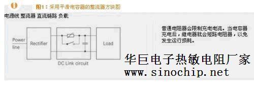
If there is no interference during operation, the above-mentioned combination of ordinary resistors and relays is sufficient to limit the charging current. However, disturbances occurring during or after charging may cause complete failure of these resistors and, consequently, complete failure of other components of the system.
In order to deal with typical faults, such as capacitor short circuit or short-circuit switch failure, it is recommended to use MZFLY series self-protective charging resistors. In faultless charging, these components act like fixed ordinary resistors, limiting the peak value of the charging current. When a fault occurs, the temperature and internal resistance of the PTC ceramic will increase with the increased ohmic losses (see Figure 2) and limit the current to a safe level.
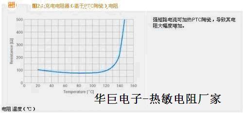
In contrast, if a fixed resistor is used as the charging current limiter, the above-mentioned failure will cause the resistor to generate a relatively high power loss, which will require a certain large size of the component, which is not economical. The following specific example (see FIG. 3) clearly illustrates this functional principle.
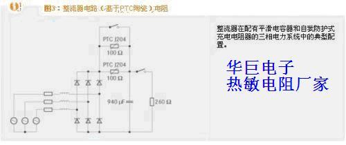
The circuit uses a three-phase bridge rectifier and connects it to a power supply with a phase conductor voltage of 400 VRMS. The capacitance of the smoothing capacitor is 940 μF. The parallel circuit contains two WMZ12A-14D130T100R type charging resistors for limiting the rush current. Also known as zero potential resistors, their rated resistance is 100 Ω at an ambient temperature of 25°C. In this case, two elements need to be connected in parallel: since the electrical energy must be transferred to the capacitor during the charging period, this will cause the individual WMZ12A-14D130T100R resistors to start heating up until the temperature rises above the allowable range, as a result of which the resistance is greatly strengthened. This situation should be avoided, otherwise the link capacitor will not be fully charged.
The number of MZFLY series components required can be calculated using the following formula:
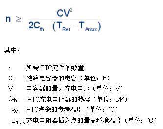
If the element WMZ12A-14D130T100R has a heat capacity of about 2 J/K and the reference temperature is 130 ℃, then the two elements can be connected in series or in parallel. Satisfying the above equation ensures that the PTC ceramic does not exceed the reference temperature before charging is completed and remains within the low resistance range.
When the 95% limit charging voltage of the capacitor is reached, the parallel MZFLY element will be short-circuited and the load will be connected (represented by a 260 Ω fixed resistor). Therefore, the performance of the parallel circuit formed by the two MZFLY elements is equivalent to a fixed resistance of 50 Ω. For fault-free charging, refer to the current-time diagram shown in Figure 4.
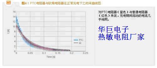
In both cases, the time profile of the charging current is almost the same. The reasons for the slight differences in current characteristics between PTC ceramics and fixed resistors are:
* PTC thermistor resistance temperature characteristics of special shape; In addition,
* The dependence of PTC ceramics on voltage at turn-on is very strong. When calculating the peak surge current, it is important to consider the voltage dependence.
After approximately 190 ms, the charging resistor is short-circuited. The energy absorption curves and the degree of heating are similarly similar (see Figure 5). The highest point of both corresponds to the energy of the capacitor when it is short-circuited.
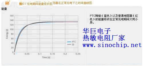
When a fault occurs, the advantage of the PTC thermistor as a current limiting element is obvious. If the relay fails to turn on, the load current will flow through the charging resistor and generate strong thermal stress, which requires the resistor to have a corresponding size. If a charging resistor based on PTC ceramics is used, its resistance rises to several 10 k due to the strong initial power loss, thus enabling the current to be limited during the occurrence of a fault (see Figure 6). After about three seconds, the current flowing through the two resistors and then through the overall circuit has dropped to several 10 mA. See Figure 7 for a comparison of the extracted energy.
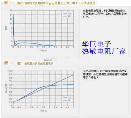
After entering the high resistance state, the PTC ceramic limits the energy absorption to a non-critical value, while the energy absorption of the fixed ohmic resistor increases linearly. In this example, to allow for temperature derating, the fixed resistor must have a power rating above 200 W to prevent overheating and subsequent damage.
Fault-capacitor shorted at the beginning of charging
The strong surge current makes the two self-protecting charging resistors highly resistive after about 150 ms, thereby limiting the current. The current flowing through the fixed resistor is limited only by the very low power line resistance, so that very high power energy conversion occurs in the fixed resistor.
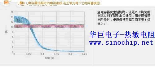
In a short time, the two self-protective charging resistors connected in parallel reach thermal equilibrium with the outside world, while the energy absorbed increases only slightly due to the high resistance value of the PTC ceramic. The resulting energy absorption is similar to that shown in FIG. 7.
The above fault-the capacitor is short-circuited at the beginning of charging-indicates that there is an extremely high load on the charging resistor. Therefore, the J201 charging resistor requires the additional use of a fixed resistor to limit the short-circuit current. However, the use of charging resistors J202 and J204 does not require any additional protection with fixed resistors.
The main circuit is a voltage-type, AC-to-DC-to-AC energy conversion inverter. Due to the energy storage circuit with large capacitance between the rectifier and inverter circuits, and the characteristic that the voltage at both ends of the capacitor cannot change abruptly, in the initial stage of power-on, the capacitor is similar to "short circuit", which will form a huge surge charging current, which will cause damage to the rectifier module due to a large current impact, it will also trip the air circuit breaker connected to the power supply end of the frequency converter due to overcurrent.
The conventional treatment method is to charge a current limiting resistor and a charging contactor (relay) in series between the rectifier and the capacitor energy storage circuit. The control of the capacitor charging process is as follows:
When the frequency converter is powered on, the capacitor is first charged by the charging resistor, which suppresses the maximum charging current. With the extension of the charging process, the charging voltage is gradually established on the capacitor. When the voltage amplitude reaches about 80% of 530V, two control processes occur. One is that the switching power supply circuit of the frequency converter vibrates, and the charging relay is directly driven by the 24V output of the switching power supply, or the relay is directly driven by this relay, turn on the coil power supply circuit of the charging contactor, and the charging contactor (relay) is closed. When the charging current limiting resistor is short-circuited, the inverter enters the standby working state. After a certain voltage is established on the capacitor, the charging current amplitude is greatly reduced, and the closing/switching current of the charging contactor is not too large. After that, the power supply of the energy storage capacitor circuit and the inverter circuit is supplied by the closed contactor contact, and the charging resistor is shorted by the normally open contact of the contactor. Second, with the establishment of the charging voltage on the capacitor, the switching power supply starts to vibrate. The CPU detects the voltage amplitude signal sent by the DC circuit voltage detection circuit, judges that the charging process of the energy storage capacitor has been completed, outputs a charging contactor action instruction, the charging contactor is electrically closed, and the charging process of the capacitor is ended.
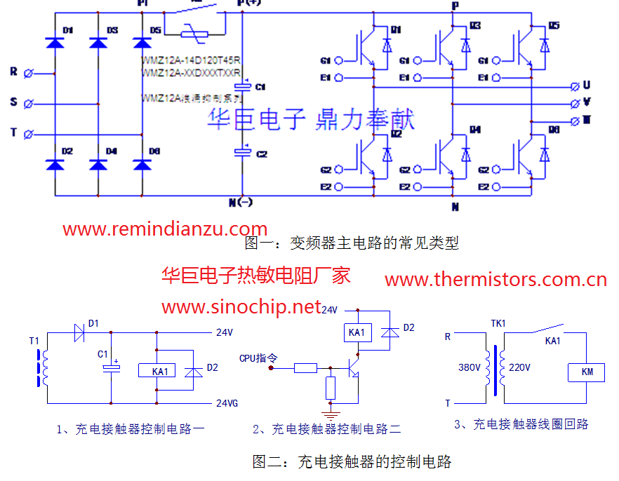
The common main circuit form of frequency converter and the control circuit of charging contactor are as follows:
For some frequency converters and high-power frequency converters, the rectifier circuit often adopts the circuit mode of a three-phase half-controlled bridge, that is, the lower three arms of the three-phase rectifier bridge are rectifier diodes, while the upper three arms use three one-way thyristors, which are "contactless switches" instead of charging contactors. The installation space is saved and the reliability of the circuit is improved. Circuit form as shown in the figure below:
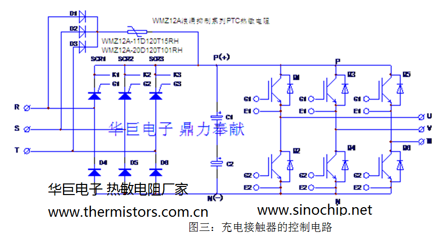
Although the charging contactor is omitted, the working principle is still the same, except that the control circuit is different. During the power-on of the inverter, D1 ∽ D6 is rectified first, and R current is limited to charge C1 and C2. At the end of the charging process, the CPU outputs the opening instructions of SCR1 ∽ SCR3, the control circuit forces the three SCR to turn on, the power-on loop composed of D1, D2, D3 and R is used, and SCR1 ∽ SCR3 and D4, D5 and D6 form a three-phase rectifier bridge, at this time, the thyristor is in a full conduction state, which is equivalent to a rectifier diode.
The opening of the thyristor requires two conditions: 1. The positive voltage between the anode and the cathode; 2. A trigger current loop is formed between K and G. The circuit is connected to the three terminals of the AC input power supply to provide unidirectional controllable rectification. During the three positive half-wave voltages of the three-phase alternating current, if the trigger current is formed at the same time, the three thyristors can be turned on. The first condition has already formed naturally, and it is only necessary to provide the second condition to control its opening.
To put it simply, as long as the SCR is provided with a trigger current (pulse or DC) during the forward voltage period-at the zero crossing of the AC voltage, the SCR can conduct well during the positive half-wave period of the AC current and rectify the input AC voltage (the same as a diode). The simplest trigger circuit is introduced from the positive stage to the G pole through a resistor, and during the positive half-wave of AC power (after zero crossing), the trigger current is introduced synchronously for the SCR, so that the SCR is turned on. Such as Dongyuan 300kW inverter, the main circuit form is the same as Figure 3, and the trigger circuit is relatively simple:
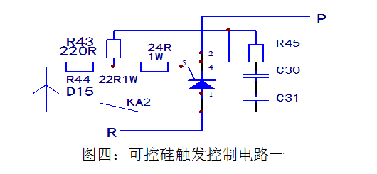
Figure 4 is one of the circuits of the SCR trigger circuit, and the other two trigger circuits are the same. The components R45, C30, C31 and other components connected in parallel at both ends of the anode and cathode of the two controlled silicon are the peak voltage absorption network to provide overvoltage protection for the controlled silicon. KA2 contacts, D15, R44 and 24R form a trigger current path. D15 is used to rectify the input voltage at half wave to avoid the impact of reverse trigger voltage/current between SCR G and K. R44 and 24R are current limiting resistors to limit the peak trigger current and protect the safety of SCR. R43 is PTC noise canceling resistor to increase the reliability of SCR operation.
When the CPU issues the SCR on command, the relay KA2 is powered on, the positive half-wave voltage is input, rectified by D15, R44 and 24R limit current, flows into the G pole of the SCR, flows out from the K pole, forms a trigger current path, and the SCR is turned on. The thyristor in the circuit is not in the working area of voltage regulation, the conduction angle is the largest, and it is in the "full conduction state". It seems to be a switching device, which is only in the two states of on and off, and there is no phase shift (voltage regulation). The third state. This is where attention needs to be paid. Therefore, the control circuit is different from the conventional phase shift control circuit and is relatively simple.
A slightly more complex SCR control circuit, such as the trigger circuit of the Delta 37kW inverter SCR, see the following figure:

After being rectified and filtered by an independent power supply winding of the switching power supply, it is used as the power supply of the thyristor trigger circuit. The control circuit consists of NE555 time base circuit, DPH2, DQ22, DQ3 trigger pulse on/off circuit, D, R three-way trigger flow circuit. After the switching power supply works, the NE555 time base circuit is connected to a multi-resonant oscillator to get power to work. Whether the oscillation pulse output from the 3 pins is sent to the three trigger circuits of the subsequent stage depends on the instruction control of the CPU. A command signal from the CPU is introduced to the input side of the photocoupler DPH2 via pin 24 of the control cable terminal DJ8. When the optocoupler output side triode conduction, NE555 oscillator pulse signal through the triode DQ22, DQ3 into the post-stage D, R trigger circuit loop. After the CPU issues the SCR turn-on instruction, the three devices DPH2, DQ22 and DQ3 are always in the on state, and the trigger pulse is always applied to the G and K of the three SCR, with a peak trigger current of about 100mA.
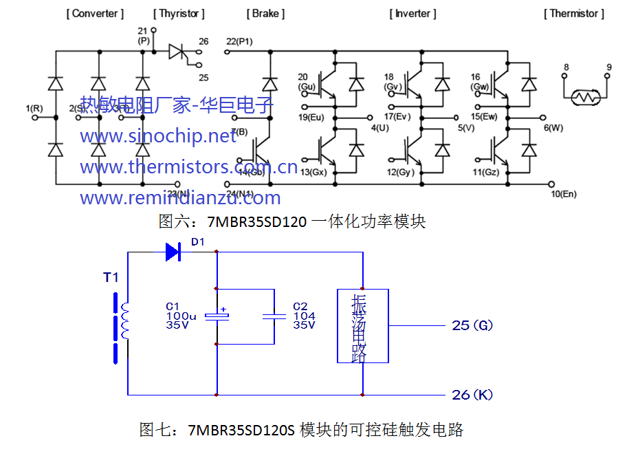
In addition, in Panasonic and Fuji low-power inverter models, another form of main circuit structure is also used to complete the initial charging control of the main circuit capacitor. This is the internal circuit structure diagram of the integrated power module of the model 7MBR35SD120. The circuit is shown in Figure VI:
The difference of the circuit is that after the three-phase rectifier bridge, a controller device is added, and charging resistors must be connected in parallel on the terminals 21 and 26. After a certain charging voltage is established on the main circuit capacitor, the trigger current is input from the terminals 25 and 26, then the thyristor is turned on and the inverter enters the standby working state.
The control circuit is generally a separate 24V winding of the switching transformer to obtain the power supply of the control circuit to obtain the control power with "floating ground. The control circuit is mostly an oscillation circuit, which increases the pulse trigger current of the thyristor device. The oscillation circuit is not a conventional phase shift trigger circuit, but provides high-frequency/density random trigger pulses to make the thyristor in a fully conductive state. Under the action of high-density trigger contact, the thyristor here is like a switch "pulled to the on position. The trigger circuit of this model, there is no actual mapping circuit on hand, can only draw a diagram according to the circuit structure for reference.
The main circuit of the inverter is the power conversion part of the asynchronous motor to provide voltage regulation and frequency modulation power supply. The main circuit of the inverter can be roughly divided into two categories:
The voltage type is a converter that converts the DC of the voltage source to AC, and the filter of the DC circuit is a capacitor.
The current type is a converter that converts the DC of the current source to AC, and its DC loop filter is an inductor. It consists of three parts, the frequency power supply is converted to DC power "rectifier", the absorption in the converter and inverter voltage pulsation "flat wave loop", and the DC power into AC power "inverter".
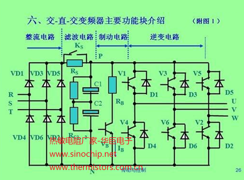
The structure and principle of voltage inverter are mainly introduced. The main circuit of voltage inverter includes three parts: rectifier circuit, intermediate DC circuit and inverter circuit. See Figure 1 for the structure of AC-DC-AC inverter.
1) Rectifier circuit: VD1 ~ VD6 form three-phase uncontrollable rectifier bridge, 220V series adopts single-phase full-wave rectifier bridge circuit; 380V series adopts bridge full-wave rectifier circuit.
2) Intermediate filter circuit: the rectified voltage is pulsating voltage and must be filtered; In addition to filtering, the filter capacitor CF also plays a decoupling role between rectification and inversion, eliminates interference and improves the power factor. As the large capacitor stores energy, high voltage exists at both ends of the capacitor in a short period of power failure, so it can only be operated after the capacitor is fully discharged.
3) Current limiting circuit: due to the large storage capacitor, the voltage at both ends of the capacitor is zero when the power supply is connected, so the charging current of the filter capacitor CF is very large at the moment of power-on, and excessive current will damage the rectifier bridge diode. In order to protect the rectifier bridge from power-on, the charging resistor RL is connected in series into the DC bus to limit the charging current. When CF is charged to a certain extent, the switch SL will short circuit RL.
4) Inverter circuit: Inverter V1 ~ V6 inverter bridge inverter DC into frequency, amplitude are adjustable alternating current, is the core part of the inverter. Commonly used inverter modules are: GTR, BJT, GTO, IGBT, IGCT, etc. Generally, modular structure is adopted with 2 units, 4 units and 6 units.
5) freewheeling diode D1 ~ D6: its main function is:
(1) The motor winding is inductive and has a reactive component, and VD1 ~ VD7 provides a channel for the reactive current to return to the DC power supply.
(2) When the motor is in the braking state, the regenerative current returns to the DC circuit through VD1 ~ VD7.
(3) The inversion process of V1 ~ V6 is that the two inverter tubes of the same bridge arm are continuously turned on and off alternately, and D1 ~ D6 are also required to provide a path during the commutation process.
6) Buffer circuit
Since the voltage between the C pole and the E pole will rise from nearly 0V to the DC voltage value UD at the moment when the inverter tubes V1 to V6 are switched from on to off each time, the excessive voltage growth rate may damage the inverter tube, and the function of the absorption capacitor is to reduce the voltage growth rate when V1 to V6 are turned off.
7) Brake unit
When the motor decelerates, the rotor speed may exceed the synchronous speed (n = 60f/P) at this time and be in the state of regenerative braking (power generation). The kinetic energy of the drag system will be fed back to the DC circuit to make the DC bus (both ends of the filter capacitor) voltage UD rise continuously (I .e. the so-called pump voltage), thus the frequency converter will generate overvoltage protection and may even damage the frequency converter, therefore, the feedback energy needs to be consumed, and the braking resistor is used to consume this part of the energy. The braking unit is composed of a switch tube and a driving circuit, and its function is to control the discharge current IB flowing through RB.
- All
- Product Management
- News
- Introduction
- Enterprise outlets
- FAQ
- Enterprise Video
- Enterprise Atlas
More information


